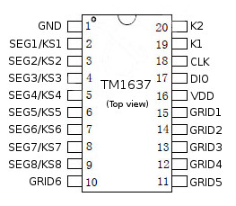
This is a 2-pin serial TM1637 chip library for Arduino, optimized for size and speed. It supports a combined LED driver controller and key-scan interface to detect one key press.
- Power CMOS process
- Display mode (8 segments × 6 digits), support common anode LED output
- Key scan (8 x 2-bit), enhanced anti-jamming button recognition circuit
- Brightness adjustment circuit (adjustable duty cycle 8)
- Two-wire serial interface (CLK, DIO)
- Oscillation mode: Built-in RC oscillator
- Built-in power-on reset circuit
- Built-in automatic blanking circuit
- Package: DIP20 / SOP20
Connect power and 2 data pins to an Arduino board DIGITAL pins:
- VDD (Power 3.3V - 5V)
- GND (Ground)
- CLK (Clock)
- DIO (Bi-directional data input/output)
The following TM1637 pins should be connected to LED's and buttons in a matrix:
- K1~K2 (Key-scan data input to read one key press after each other)
- SEG/GRID (Output for LED matrix)
| Pin | TM1637 | Arduino UNO / Nano / Micro / Pro Micro / Leonardo / Mega2560 | WeMos D1 & R2 / Node MCU | WeMos LOLIN32 |
|---|---|---|---|---|
| 1 | VCC | 5V (or 3.3V) | 3V3 | 3V3 |
| 2 | GND | GND | GND | GND |
| 3 | CLK | 2 (DIGITAL pin) | D2 | 0 |
| 4 | DIO | 3 (DIGITAL pin) | D3 | 4 |
- Check maximum regulator / diode current to prevent a burnout when using lots of LED's. Some boards can provide only 100mA, others 800mA max.
The TM1637 communicates with a MCU serial by using two wires:
- DIO (bi-directional input/output pin)
- SCL (Clock pin)
Note: The serial interface is not compatible with I2C or TWI, because no device address with read/write bit is used.
Arduino IDE | Examples | Erriez TM1637 button and LED driver:
Initialization
// Include TM1637 library
#include <ErriezTM1637.h>

// Connect display pins to the Arduino DIGITAL pins
#define TM1637_CLK_PIN   2
#define TM1637_DIO_PIN   3

// Create tm1637 object
TM1637 tm1637(TM1637_CLK_PIN, TM1637_DIO_PIN);

void setup()
{
    // Initialize TM1637
    tm1637.begin();
}
Display on/off
// Turn display off
tm1637.displayOff();

// Turn display on
tm1637.displayOn();
Turn all LED's off
// Turn all LED's off
tm1637.clear();
Get keys
// Get 8-bit key-scan
uint8_t keys = tm1637.getKeys();
Write Byte to display register
// Write segment LED's to the first display registers 0x00..0x0F with value 0x00..0xff to
// display numbers and characters. Just an example which depends on the hardware:
tm1637.writeData(0x01, 0x01);
Write buffer to display registers
// Creat buffer with LED's
uint8_t buf[] = { 0b10000110, 0b00111111, 0b00111111, 0b00111111, 0b00111111, 0b00111111};

// Write buffer to TM1637
tm1637.writeData(0x00, buf, sizeof(buf));The library uses optimized pin control for AVR targets. Other targets uses the default digitalRead() and digitalWrite() pin control functions.
Output Benchmark example:
| Board | CLK | Read keys | Write Byte | Write 16 Bytes buffer | Clear display |
|---|---|---|---|---|---|
| Pro Mini 8MHz | 84kHz | 352us | 344us | 1080us | 1072us |
| UNO 16MHz | 170kHz | 156us | 152us | 496us | 480us |
| WeMos D1 & R2 80MHz | 205kHz | 261us | 137us | 396us | 396us |
| WeMos D1 & R2 160MHz | 300kHz | 233us | 96us | 275us | 271us |
- The Benchmark example uses Erriez Timestamp library.
Please refer to the Wiki page.


